CCIE Challenge 1: DMVPN FVRF local breakout
So, this is the first CCIEChallenge created by me. You need to achieve the following to pass the challenge:
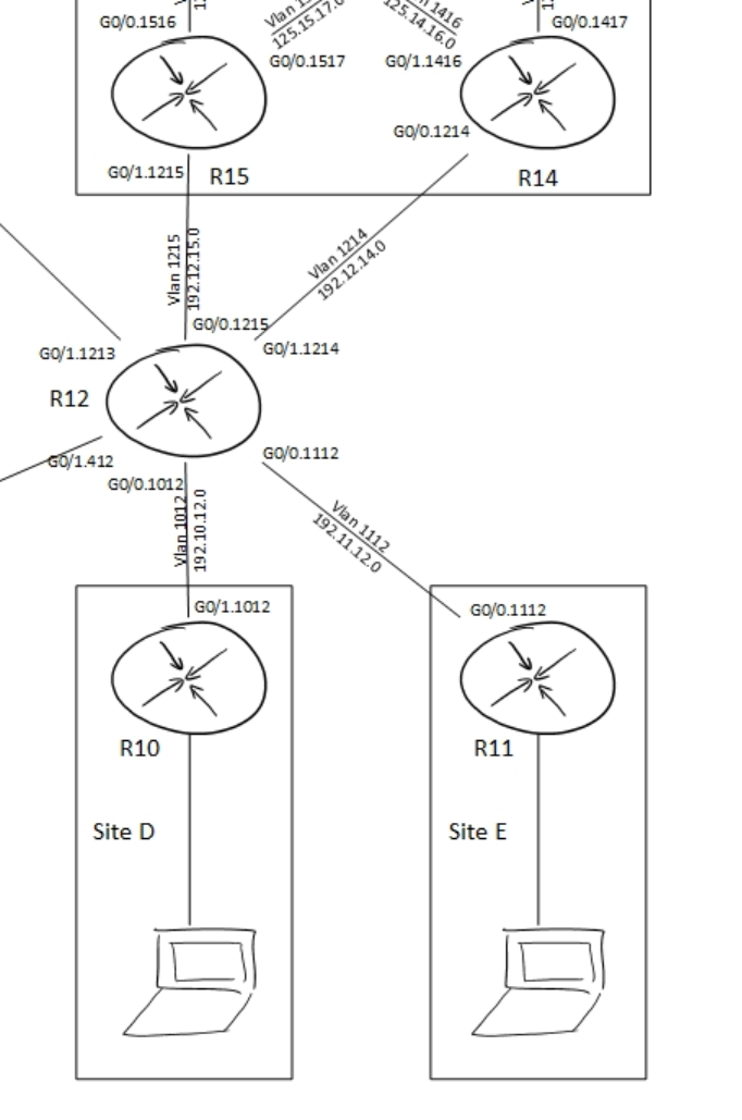
In the topology, please ignore R15. It has no role in this assignment.
The initial config files can be downloaded here
- Set up a DMVPN between R14 (hub), R10 and R11 (spokes)
- This DMVPN needs to use the default route the routers have received from R12.
- The links between R12 and the other routers are part of the INTERNET VRF, the DMVPN should be member of the global routing table.
- Protect the DMVPN using the following IPsec characteristics:
- pre-shared key: CCIECHALLENGE
- ISAKMP parameters: AES, SHA-1, Group 5
- IPsec transform-set: AES 192, SHA256
- Tunnel key & ID: 123
- NHRP authentication: cisco
- R14 should announce a default route to R10 and R11 as well as the 10.0.0.0/8 summary.
- You are allowed one static route for the purpose of announcing the default to the spokes.
- All traffic between DMVPN devices needs to travel directly between spokes.
- Traffic from R1 behind R10 destined to the internet should not traverse the Spoke.
- Test this using a traceroute from R1.
- You are not allowed to use static routing.
- You are not allowed to leak INTERNET routes into the global table.
- Apply NAT if and where necessary.
- Traffic from R2 behind R11 destined to the internet should traverse the Spoke.
- Test this using a traceroute from R2.
- You are not allowed to use static routing.
- You are not allowed to leak routes between VRFs.
- Apply NAT if and where necessary.
- You are not allowed to make any modifications to R12.
- You are not allowed to introduce any new routing protocols.
Match the following outputs:
R10#show ip route bgp
[snip]
Gateway of last resort is 100.0.0.14 to network 0.0.0.0

B*    0.0.0.0/0 [20/0] via 100.0.0.14, 00:00:46
      10.0.0.0/8 is variably subnetted, 5 subnets, 3 masks
B        10.0.0.0/8 [20/0] via 100.0.0.14, 00:05:08
!
R10#trace 10.11.0.1 so g 0/2
Type escape sequence to abort.
Tracing the route to 10.11.0.1
VRF info: (vrf in name/id, vrf out name/id)
  1 100.0.0.11 22 msec 15 msec 15 msec
R11#sh ip route bgp
[snip]
Gateway of last resort is 100.0.0.14 to network 0.0.0.0

B*    0.0.0.0/0 [20/0] via 100.0.0.14, 00:01:11
      10.0.0.0/8 is variably subnetted, 4 subnets, 3 masks
B        10.0.0.0/8 [20/0] via 100.0.0.14, 00:05:33
!
R11#trace 10.10.0.1 so g 0/2
Type escape sequence to abort.
Tracing the route to 10.10.0.1
VRF info: (vrf in name/id, vrf out name/id)
  1 100.0.0.10 11 msec 24 msec 23 msec
R1#trace 8.8.8.8 num
Type escape sequence to abort.
Tracing the route to 8.8.8.8
VRF info: (vrf in name/id, vrf out name/id)
  1 10.10.0.1 1 msec 1 msec 1 msec
  2 192.10.12.12 17 msec *  15 msec
R2#trace 8.8.8.8 num
Type escape sequence to abort.
Tracing the route to 8.8.8.8
VRF info: (vrf in name/id, vrf out name/id)
  1 10.11.0.1 1 msec 5 msec 1 msec
  2 100.0.0.14 15 msec 28 msec 24 msec
  3 192.12.14.12 38 msec *  42 msec
Solution
First off, the tasks asks you to create a DMVPN between R10, R11 and R14, where R14 is the hub. The underlay connectivity is provided in a VRF. The overlay however should not be part of the VRF, but should be in the global table.
This requirement calls for the tunnel vrf command. This tells the router that the tunnel source interface is in a VRF, but the tunnel itself should not be part of that VRF. (If you want to make the tunnel part of the VRF you should use the vrf forwarding command under the tunnel interface)
The assignment also asks for direct spoke to spoke communication while the hub should announce only two summaries to the spokes. This means you have to use phase 3 DMVPN. Take a good look at the traceroute results between R10 and R11. These tracroutes should tell you that you need to disable icmp unreachable rate limiting (no ip icmp rate-limit unreachable).
Since the DMVPN needs to be protected by IPsec we have to define crypto policies. Because the tunnel interface is in a VRF we need to specify the VRF for the ISAKMP key. If you want to read more on how to do this, please read IPSec for DMVPN with Front Door VRFs.
Since we’re not allowed to introduce any new routing protocols we’ll have to make do with what we’ve got. In this case BGP has already been set up for us. Even the BGP connectivity between the hub and spokes has been preconfigured. What has not been preconfigured is the network advertisements on the various routers.
Setting up the DMVPN and routing however isn’t the main part of this assignment. You should be well familiar with those steps. The main part of this challenge is the internet connectivity for R1 and R2 (the clients behind R10 and R11 respectively). The assignment specifies two ways to get to the internet:
- Direct local breakout (R1 via R10 to the internet)
- Internet via DMVPN hub (R2 via R11, R14 to the internet)
Using route leaking between the VRFs would be the easiest solution for this. However, route leaking is (partially) prohibited. In the case of the local internet breakout it is allowed to leak global routes into the INTERNET table, but you are not allowed to leak INTERNET routes into the global table. This means we have to use some other means of getting our traffic into the INTERNET table for traffic originating at R1. Return traffic will be able to return to R1 because of the leaking into the INTERNET table.
The solution chosen for this is policy based routing. As the restrictions state, no other routing protocol is allowed, but PBR isn’t a routing protocol and therefore allowed in this case. Aside from PBR we also need NAT to translate a global address to an INTERNET address since R12 wouldn’t know how to reach the address of R1 in this case. (It would also be allowed in this case to advertise the IP addresses of R1 to R12 since we’re allowed to leak global addresses into the INTERNET table)
For traffic traversing the hub route leaking is prohibited completely. This means we need to use PBR on the outside too.
The relevant configs are posted below:
R10:

vrf definition INTERNET
 rd 1:1
 !
 address-family ipv4
  route-replicate from vrf global unicast connected
 exit-address-family
!
no ip icmp rate-limit unreachable
!
crypto keyring FVRF vrf INTERNET
  pre-shared-key address 0.0.0.0 0.0.0.0 key CCIECHALLENGE
!
crypto isakmp policy 1
 encr aes
 authentication pre-share
 group 5
!
!
crypto ipsec transform-set DMVPN esp-aes 192 esp-sha256-hmac
 mode transport
!
crypto ipsec profile DMVPN
 set transform-set DMVPN
!
interface Tunnel0
 ip address 100.0.0.10 255.255.255.0
 no ip redirects
 ip mtu 1400
 ip nhrp authentication cisco
 ip nhrp network-id 123
 ip nhrp nhs 100.0.0.14 nbma 192.12.14.14 multicast
 ip nhrp shortcut
 ip tcp adjust-mss 1360
 tunnel source GigabitEthernet0/1.1012
 tunnel mode gre multipoint
 tunnel key 123
 tunnel vrf INTERNET
 tunnel protection ipsec profile DMVPN
!
interface GigabitEthernet0/1.1012
 encapsulation dot1Q 1012
 vrf forwarding INTERNET
 ip address 192.10.12.10 255.255.255.0
 ip nat outside
 ip virtual-reassembly in
!
interface GigabitEthernet0/2
 ip address 10.10.0.1 255.255.255.0
 ip nat inside
 ip virtual-reassembly in
 ip policy route-map PBR
 duplex auto
 speed auto
 media-type rj45
!
router bgp 65010
 bgp log-neighbor-changes
 no bgp default ipv4-unicast
 neighbor 100.0.0.14 remote-as 65145
 !
 address-family ipv4
  network 10.10.0.0 mask 255.255.255.0
  neighbor 100.0.0.14 activate
 exit-address-family
 !
!
ip nat inside source list NAT interface GigabitEthernet0/1.1012 vrf INTERNET overload
!
ip access-list extended NAT
 deny   ip any 10.0.0.0 0.255.255.255
 permit ip 10.10.0.0 0.0.0.255 any
ip access-list extended POLICY
 deny   ip any 10.0.0.0 0.255.255.255
 permit ip 10.10.0.0 0.0.0.255 any
!
!
route-map PBR permit 10
 match ip address POLICY
 set ip default vrf INTERNET next-hop 192.10.12.12
!
R11:

no ip icmp rate-limit unreachable
!
crypto keyring FVRF vrf INTERNET
  pre-shared-key address 0.0.0.0 0.0.0.0 key CCIECHALLENGE
!
crypto isakmp policy 1
 encr aes
 authentication pre-share
 group 5
!
crypto ipsec transform-set DMVPN esp-aes 192 esp-sha256-hmac
 mode transport
!
crypto ipsec profile DMVPN
 set transform-set DMVPN
!
interface Tunnel0
 ip address 100.0.0.11 255.255.255.0
 no ip redirects
 ip mtu 1400
 ip nhrp authentication cisco
 ip nhrp network-id 123
 ip nhrp nhs 100.0.0.10 nbma 192.12.14.14 multicast
 ip nhrp shortcut
 ip tcp adjust-mss 1360
 tunnel source GigabitEthernet0/0.1112
 tunnel mode gre multipoint
 tunnel key 123
 tunnel vrf INTERNET
 tunnel protection ipsec profile DMVPN
!
router bgp 65011
 bgp log-neighbor-changes
 no bgp default ipv4-unicast
 neighbor 100.0.0.14 remote-as 65145
 !
 address-family ipv4
  network 10.11.0.0 mask 255.255.255.0
  neighbor 100.0.0.14 activate
 exit-address-family
 !
!
R14:

crypto keyring FVRF vrf INTERNET
  pre-shared-key address 0.0.0.0 0.0.0.0 key CCIECHALLENGE
!
crypto isakmp policy 1
 encr aes
 authentication pre-share
 group 5
!
crypto ipsec transform-set DMVPN esp-aes 192 esp-sha256-hmac
 mode transport
!
crypto ipsec profile DMVPN
 set transform-set DMVPN
!
interface Tunnel0
 ip address 100.0.0.14 255.255.255.0
 no ip redirects
 ip mtu 1400
 ip nat inside
 ip nhrp authentication cisco
 ip nhrp map multicast dynamic
 ip nhrp network-id 123
 ip nhrp redirect
 ip virtual-reassembly in
 ip tcp adjust-mss 1360
 ip policy route-map PBR-INSIDE
 tunnel source GigabitEthernet0/0.1214
 tunnel mode gre multipoint
 tunnel key 123
 tunnel vrf INTERNET
 tunnel protection ipsec profile DMVPN
!
interface GigabitEthernet0/0.1214
 encapsulation dot1Q 1214
 vrf forwarding INTERNET
 ip address 192.12.14.14 255.255.255.0
 ip nat outside
 ip virtual-reassembly in
 ip policy route-map PBR-OUTSIDE
!
router bgp 65145
 bgp log-neighbor-changes
 no bgp default ipv4-unicast
 neighbor 100.0.0.10 remote-as 65010
 neighbor 100.0.0.11 remote-as 65011
 !
 address-family ipv4
  network 0.0.0.0
  aggregate-address 10.0.0.0 255.0.0.0 summary-only
  neighbor 100.0.0.10 activate
  neighbor 100.0.0.11 activate
 exit-address-family
 !
!
ip nat inside source list NAT interface GigabitEthernet0/0.1214 vrf INTERNET overload
ip route 0.0.0.0 0.0.0.0 Null0
!
ip access-list extended NAT
 deny   ip 10.0.0.0 0.255.255.255 10.0.0.0 0.255.255.255
 permit ip 10.0.0.0 0.255.255.255 any
ip access-list extended POLICY-INSIDE
 deny   ip 10.0.0.0 0.255.255.255 10.0.0.0 0.255.255.255
 permit ip 10.0.0.0 0.255.255.255 any
ip access-list extended POLICY-OUTSIDE
 permit ip any 10.0.0.0 0.255.255.255
!
route-map PBR-OUTSIDE permit 10
 match ip address POLICY-OUTSIDE
 set global
!
route-map PBR-INSIDE permit 10
 match ip address POLICY-INSIDE
 set ip default vrf INTERNET next-hop 192.12.14.12
!