Back to back multipod
You might have seen my ACI lab in a previous post. I’ve installed that lab two years ago and ever since it has seen some heavy usage. It also lost some hardware due to ACI 5.x being installed on it and the Gen 1 hardware not supporting that version. Since the lab is used by me and co-workers to perform tests, training and lots and lots more it was time for a winter cleaning. This immediately was a nice chance to try the newest design option within ACI.
Since ACI 5.2 it is possible to create a multi-pod fabric without using an IPN network. For smaller customers this is an ideal solution. There are some limitations though:
- You can only build two pods
- Anything that would require a network connected to Spine switches is not supported in combination with back-to-back multi-pod. That means no multi-site, GOLF or remote physical leafs.
- First generation spines are not suppported
It is possible to move to an actual IPN network when you already have back-to-back multipod configured. However, this is a disruptive move. If you have plans for the near future to install additional pods or sites you will be better of investing in an Interpod Network immediately.
If, however, you expect that two pods will be sufficient for you for the forseeable future, the back-to-back multipod will save you quite some money.
ACI has come a long way since the first introduction of multi-pod and this back-to-back multipod is even easier than regular multipod. As you can imagine, you don’t have to configure an IPN network anymore. Gone is that pesky multicast :-)
back to back multipod requires you to correctly cable the spines together and then configure it from the APIC.
It’s smart to start with a cabling and IP scheme before you start configuring. I tried it without and had to take care that I did it correctly.
Preparation
For this lab I created the following topology. Keep in mind that I would normally use /30 or /31 IP ranges to configure these connections. For now this was just “easy”
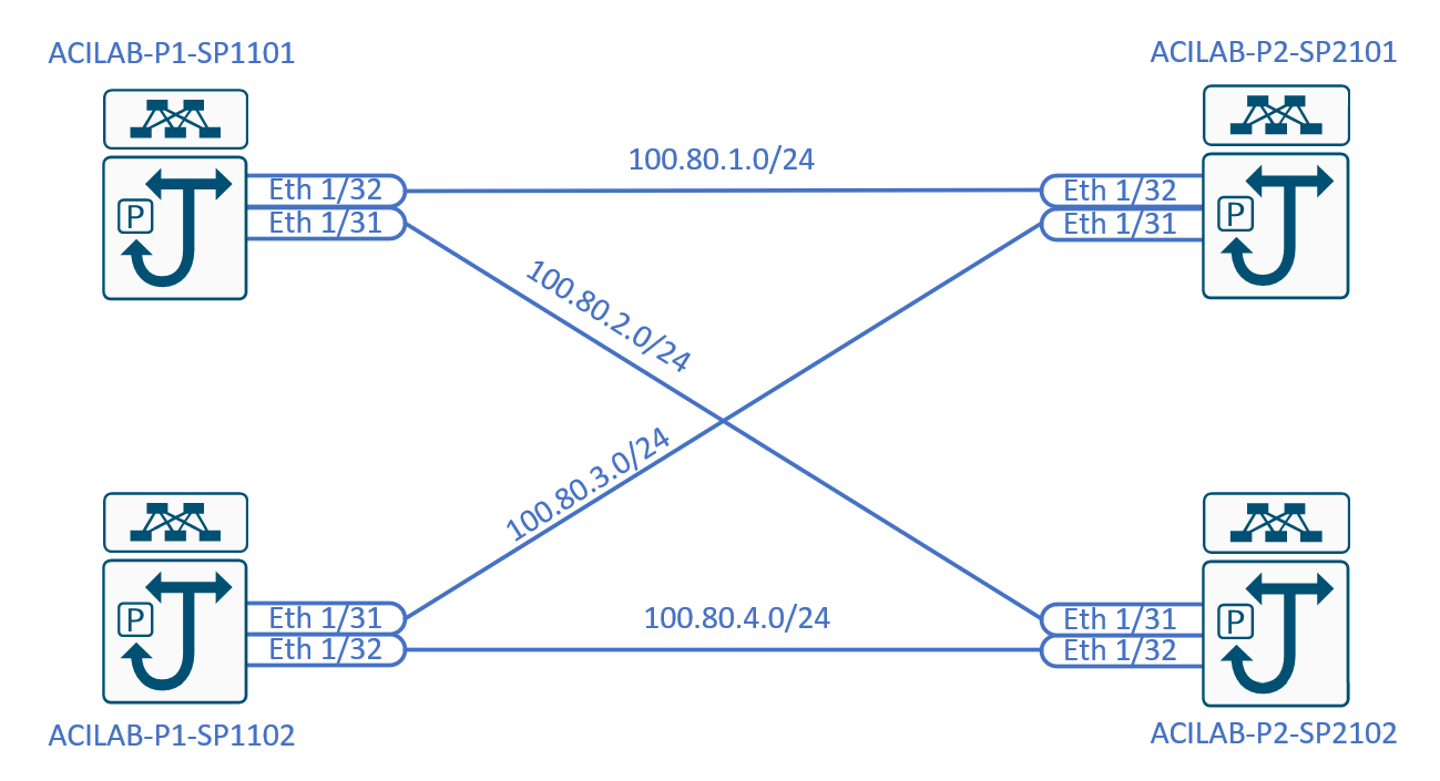
The shown topology actually is the recommended topology for a back to back design. Use two spines in each pod and fully mesh them. If you have more than two spines in each pod you can use those as well, but it’s not required. The minimum, for obvious reasons is a single spine, single connection. I would not recommend that (also for obvious reasons)
Aside from this topology it’s good practice to collect some information before you start configuring the fabric.
- POD 1:
- Internal TEP pool: 100.64.0.0/16
- External TEP pool: 100.66.1.0/24
- Spine configuration:
- Spine 1101:
- Router ID: 100.67.1.101
- Loopback IP: 100.67.1.101/32
- Spine 1102:
- Router ID: 100.67.1.102
- Loopback IP: 100.67.1.102/32
- Spine 1101:
- POD 2:
- Internal TEP pool: 100.65.0.0/16
- External TEP pool: 100.66.2.0/24
- Spine configuration:
- Spine 2101:
- Router ID: 100.67.2.101
- Loopback IP: 100.67.2.101/32
- Spine 2102:
- Router ID: 100.67.2.102
- Loopback IP: 100.67.2.102/32
- Spine 2101:
- OSPF settings:
- Area type: Regular
- Area ID: 0
- Interface Policy:
- Network type: Point-to-Point
- Timers: Default
- BFD: Enabled
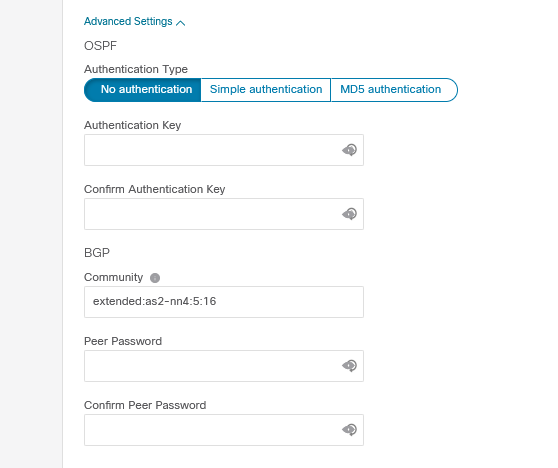
- Advanced settings:
- OSPF Authentication: none (default)
- BGP settings:
- Community: extended:as2-nn4:5:16 (this is default)
- Peer password: none (default)
This is quite a lot of information, but to be fair, it’s the same as regular multi-pod configurations. This should not be new if you have ever configured a multipod ACI fabric before.
The Internal TEP pool is used to address devices within the underlay of the fabric. The external TEP is used create Dataplane Tunnel EndPoint Addresses and Unicast TEP addresses. These will automatically be populated when you fill in a subnet.
The OSPF settings are also settings you’re used to configuring. This time, because it’s back to back you don’t really need to take existing networks into consideration. I would recommend always using a regular type area with ID 0. As for the OSPF interface profile I would recommend using point-to-point interfaces and BFD.
In most cases you can keep the advanced settings default, unless you want to protect it using passwords and authentication. Please don’t modify the Community string unless you really know what you’re doing.
Configuration
We will configure the multi-pod using the GUI. I believe this shows the process best. Of course you can also automate this using REST calls, Ansible or other automation methods.
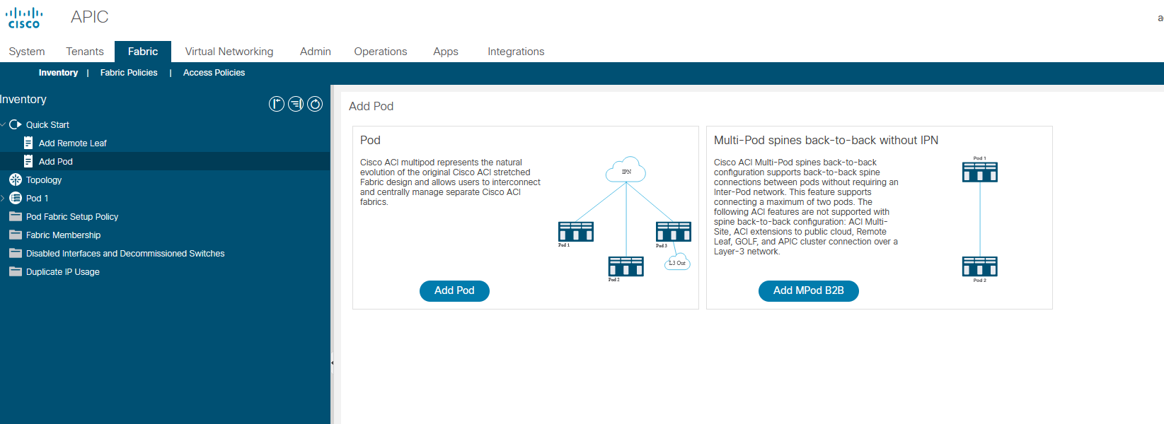
To start the correct wizard choose the “Add MPod B2B” option on the Quick start screen of the Fabric, Inventory menu. This will start the back-to-back multipod configuration wizard.
Configure IP connectivity
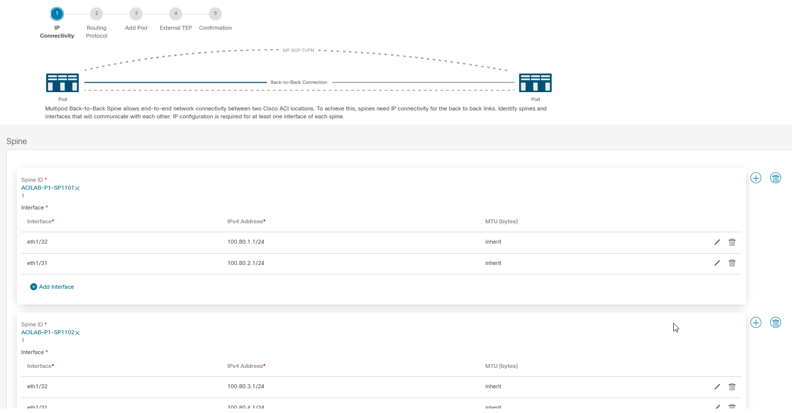
Your first task will be to configure the Spine nodes and interfaces in Pod1. This is the pod you already have running, so you can select the right switches and interfaces. To be fair I don’t like the fact that you can only select them, I’d rather just type them in. But this is likely less error prone.
To add another switch use the Plus icon to the right of the screen, behind the scare box containing the first spine. To add interfaces simply click the “Add Interface” button.
Once you’re done you can continue to the second step, which is configuring the routing protocol.
Configure routing protocols
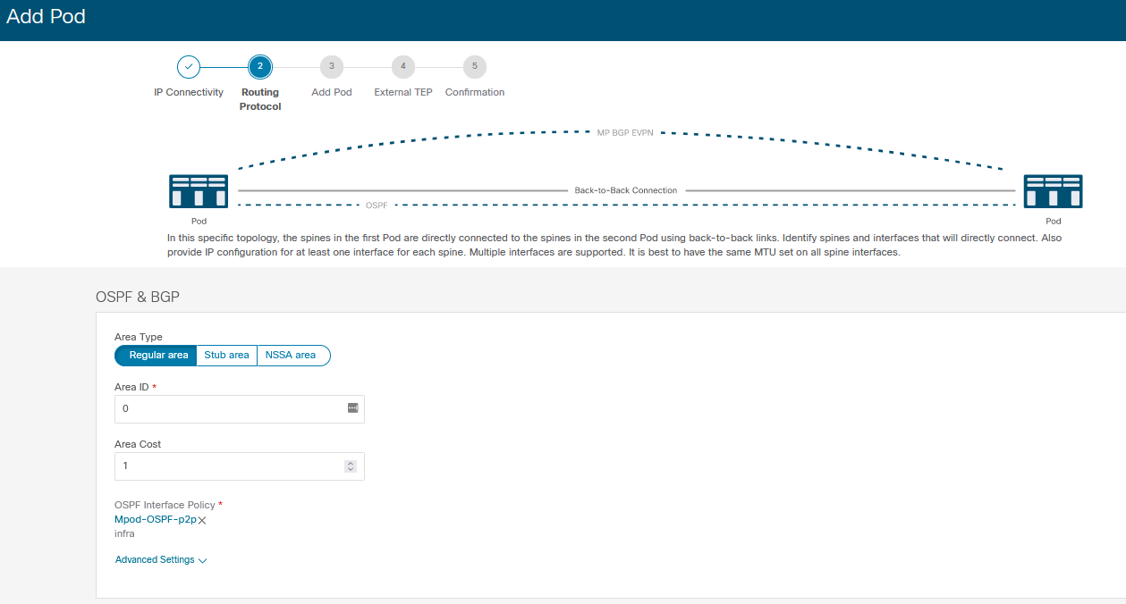
Here you configure the OSPF settings and the advanced settings. You will also need to select an OSPF interface policy. I would recommend creating one specifically for the multipod configuration. The sole reasoning behind this is that if you ever modify your ‘default’ OSPF interface profile you might unintentionally break your multipod when it uses that profile. Using a specific profile just for your multipod prevents you from making that error.
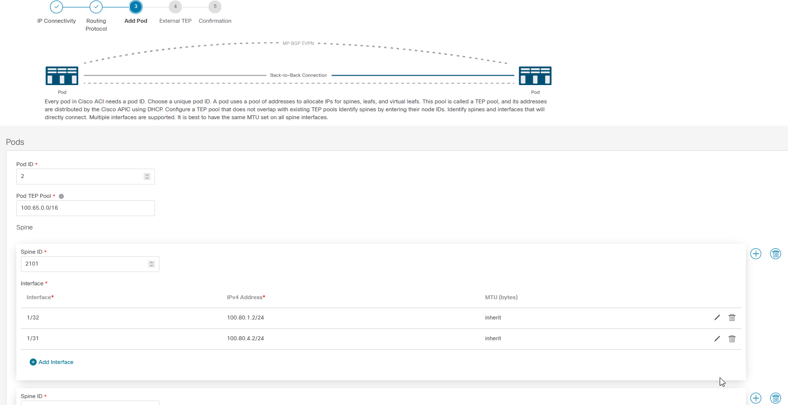
Add a pod
Once you’ve configured the routing protocols you can add the second pod. You need to give it its number and its internal TEP pool. Aside from that it’s more or less the same as the first step. You need to select the Spines and their interfaces and assign the correct IP addresses to them. Since these Spines haven’t been discovered yet you need to put in their switch numbers manually and manually enter the interface numbers.
Take very good care here. When you configure these device numbers and interfaces you must know for sure which switch is going to be which. You are pre-configuring the devices. The APIC will automatically push the interface configuration to the switches as soon as it discovers the switches. That means that when you register a switch and it’s a different one from the one you thought it is, it will get the wrong IP information. After that it won’t be available anymore. If the second pod actually is in a different site this might require you to take a trip to that site.
To prevent this from happening double check your topology diagram, your configured switches, interfaces and IP addresses. When registering the switch also double check its serial number. This is experience talking…
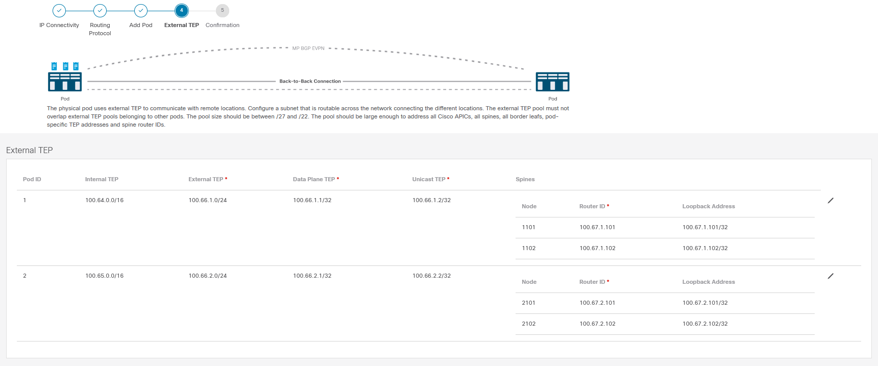
Configure External TEP
This is the last configuration step. Here you configure the external TEP and the router ID information of each Spine. You can just fill out the information based on what you’ve prepared.
Take care that the loopback address does not overlap the external TEP pool. I always try to keep the loopback and router ID the same.
Confirmation
The last screen is a summary of all you have entered. You can move between the earlier steps when you need to modify something. Once you’re sure it’s all correct you can submit the configuration.
Discover the switches
Discovering the switches is the same as usual. In the menu under Fabric Membership the new switches should appear. Keep in mind that you will only discover switches when they are cabled. A spine needs to be connected to a leaf switch for the multipod process to start. This is just how it works.
You can register the switches and they will become part of the fabric. Just ensure you register them in the right pod and ensure you use the same switch ID for the right switch!
Have fun with B2B MPOD!
So what do you think? Is this design something you will deploy often, or is it just some corner case?