ACI PBR Firewall Insertion
I’m working on a series of posts concerning service graphs in ACI. In order for these posts I configured some stuff in my lab to demonstrate these functions. The series will take a long time for me to complete. To bridge the time between posts I decided to create a post about the PBR firewall integration I did in my lab.
This post does not cover reasons for using PBR in great detail, but in my opinion the PBR type of service graphs are the most likely type to be encountered.
PBR Service Graphs
PBR service graphs use Policy Based Redirect (notice the use of Redirect instead of Routing) to redirect traffic toward a L4-L7 device. The traffic that needs to be redirected is defined within the contract in ACI. Redirection can be done on both L2, L3 and L4, which is why it is redirecting instead of routing.
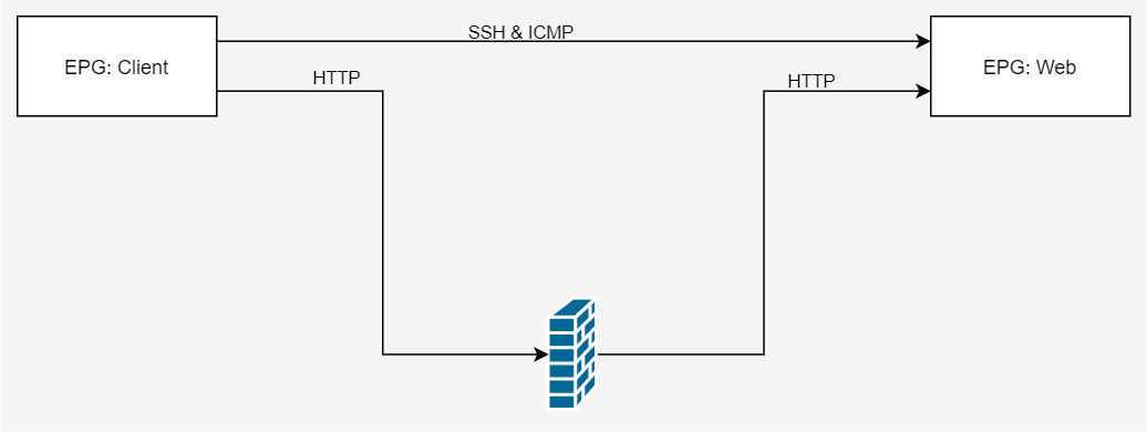
In the image below you see two EPG’s. These EPG’s must be able to communicate using SSH, ICMP and HTTP. I would like the HTTP traffic to go through the firewall, but for SSH and ICMP I don’t have that requirement. So those flows can go directly to the destination EPG.
Requirements
To be able to implement this design we need the following:
- 4 Bridge Domains:
- 2 EPG’s
- 1 contract
- 2 Subjects
- Inside and Outside interface on the firewall
- MAC addresses and IP addresses of the firewall interfaces.
- (Physical) interfaces on the switches
I’ll use the following values:
- Bridge Domains:
- Client (vlan-10)
- FW_CLIENT (vlan-11)
- FW_SERVER (vlan-19)
- WebServer (vlan-20)
- EPG’s:
- Client
- Web
- Contract:
- Client_to_Web
- Subject1: Redirect
- Subject2: SSH_ICMP
- Client_to_Web
- Inside firewall interface (web):
- GigabitEthernet 0/1:
- MAC: 000c.29ae.9152
- IP: 192.168.19.1
- GigabitEthernet 0/1:
- Outside firewall interface (client):
- GigabitEthernet 0/0:
- MAC: 000c.29ae.9148
- IP: 192.168.11.1/24
- GigabitEthernet 0/0:
- Interfaces on the switches:
- 201/1/50
- 202/1/50
For your information, in regards to the physical interfaces. I cheated a bit. I’m using an ASAv on an ESX machine. However, for this lab I’m not using VMM integration, so I’m using static encaps of EPGs on ports. This works fine for PBR service graphs.
Configuration
To configure this Service Graph there are several steps to complete:
- Create the Bridge Domains and EPGs
- Create the L4-L7 device
- Create the Policy Based Redirects
- Create a Service Graph Template
- Deploy the Service Graph Template
I’m assuming you know how to define Bridge Domains and EPG’s, so I’m not covering the details here. I’ve defined the Bridge Domains using default settings.
Create the L4-L7 device
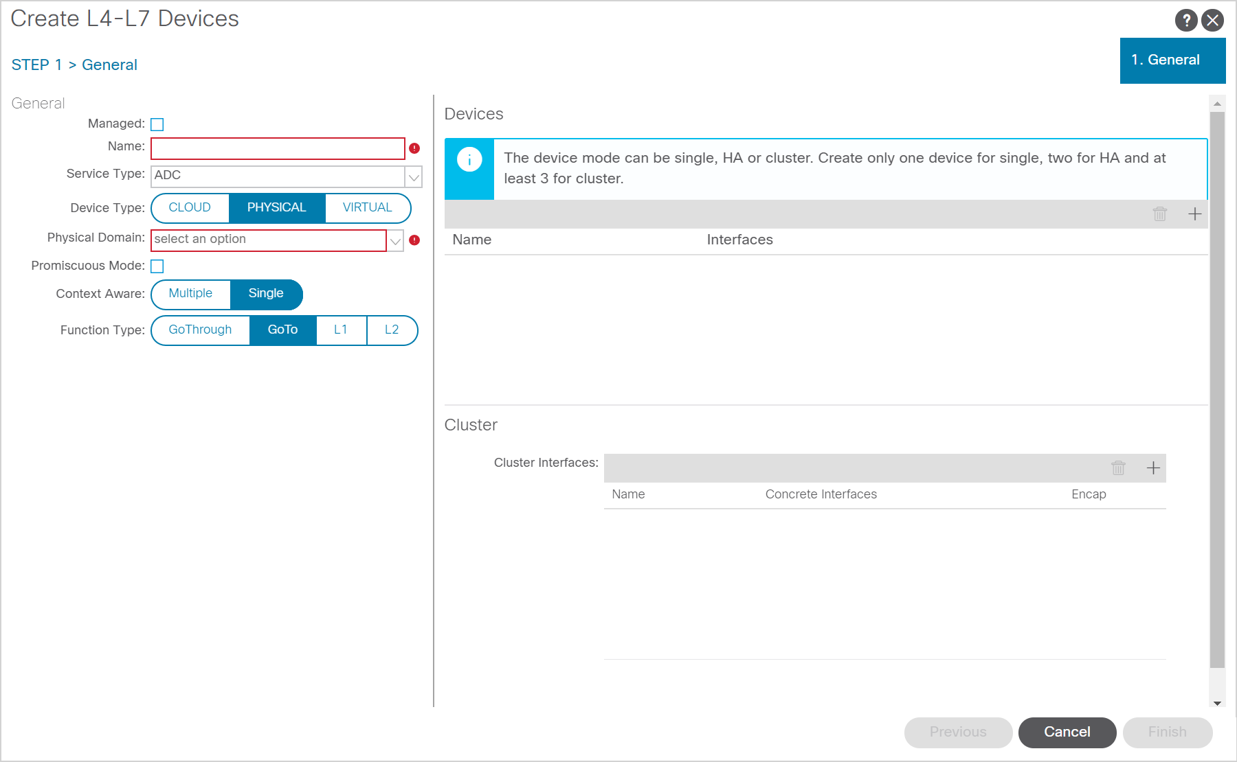
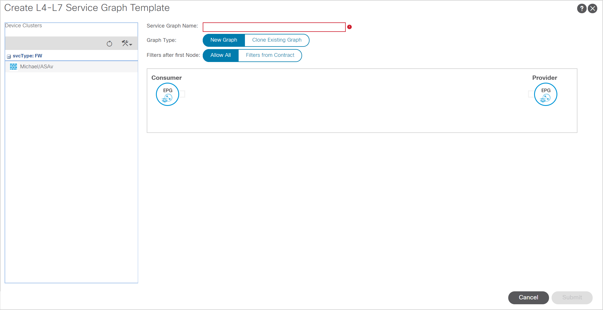
When you create the L4 to L7 device you have to create it under your tenant, under Services, Devices. Here you have to deselect the “managed” checkbox. After you deselected the checkbox you should be presented with the screen as shown above.
On this screen you have to define the name and select the type of device. Since we’re creating a firewall service graph we will select ‘Firewall’ here.
As for the Device Type, even though I’m using an ASAv appliance I needed to select PHYSICAL device type. This is because I’m using static bindings instead of integration with VMware. If you do have VMware integration you can select VIRTUAL here and select the right domain. You should be able to select the deployed ASAv then and select the right interfaces.
The context aware mode is Single as this device will not be shared between tenants. The function type is GoTo as this firewall is implemented in a routed mode.
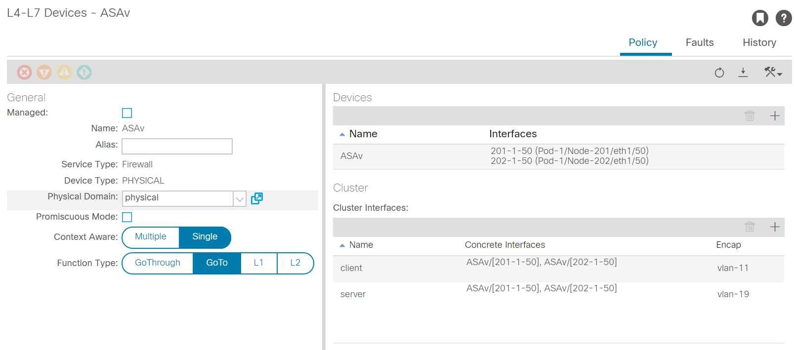
Next, we move on to the right side of the screen. The first time I configured this I was a bit confused as to what I had to configure here. I think I was thrown off track due to the design of the interface, but first you have to add a ‘concrete’ device. This is the actual device you will connect. When it’s a cluster consisting of multiple (physical) devices you have to add them all here. The interfaces are the interfaces on which the devices are connected. In my case I connected the ESX environment on ports 201/1/50 and 202/1/50, so I had to define these interfaces as my ‘device’ interfaces. I named these 201-1-50 and 202-1-50 respectively.
The cluster interfaces you have to define are comparable to the static port mappings you’ll do in a regular EPG. Define the name of the interface, the concrete interfaces they should be mapped to and the Encap you’ll use for the traffic. In the end you should have a configuration comparable to the following screenshot:
Create Policy Based Redirects
To enable ACI to send traffic to the L4-L7 device it needs to know where to send it to. For this you need to define the PBR objects. In this object you define the IP and MAC address of the L4-L7 device. As we have two interfaces on the firewall, we’ll define two redirects. One for the client side and one for the server side.
To create these redirects you have to go to Policy, Protocol, L4-L7 Policy-Based Redirect in your tenant.
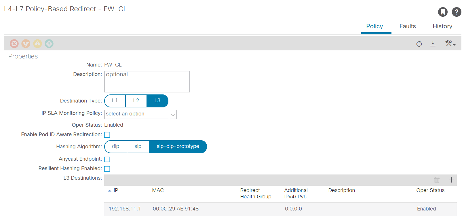
Since we’re building a L3 service we have to select L3 as destination type. If you’re building a L2 redirect you could use L2 as destination type. Add a L3 destination. For this you will need both the IP address and the MAC address of the right interface on the firewall.
Make sure you use a recognizable name for the PBR as you will need to use this later
You can use the defaults for most implementations here. If you have a multi-pod and want to keep traffic local to the pod you can enable “Pod ID Aware Redirection”, this enables you to specify a POD ID per L3 destination. You’ll only have this option for L3 service graphs.
If you use an anycast endpoint you won’t need to be aware of the pod ID as the anycast IP address should be available in both pods.
Create a Service Graph Template
Next you should define a template for the service graph. This template defines which devices will be used in the service graph. In our case this will be a very simple one node service graph, but you can create more complex ones in which you put multiple devices in succession. Like a loadbalancer after a firewall.
Creating a service graph template is easy. Within your tenant you have to go back to Services, L4-L7. Then go to Service Graph Templates. Here you can create a new service graph template.
Give the Servicegraph a name and insert the right devices and you’ve got your service graph template.
Deploy the Service Graph Template
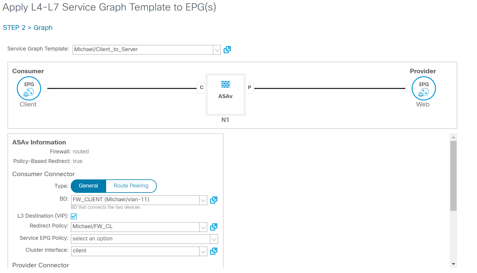
Once you’ve defined the Service Graph Template you have to deploy it. You can do this by right clicking on the freshly created template and choosing “Apply L4-L7 Service Graph Template”. You’ll get the following screen.

In this screen you’ll have to select the EPG’s between which the Service Graph will be applied. You also have to define the contract which will tell ACI which traffic should be redirected. You can select all traffic here, or define a contract selecting specific traffic like HTTP. Once you click next you have to define the consumer and provider connectors. Use the BD which connects the firewall and use the redirect policy and cluster interface that match to the right BD and firewall interface.
Now the service graph should be applied and should be working. You can verify this by looking at your EPG’s to see whether the contract was applied and whether the applied contract has the specified subject and filters. By default the subject created by ACI is called subject. You might want to change this.